
перевод
Chapter 5. Interior Planking.
For grinding, I used a pipe insulation material (insulation) by gluing it in half.


Then, he also glued sandpaper, 150 and 240 grain. And it turned out such tools. The main thing is that the corners of the surface are rounded.

This design allows you to grind concave surfaces, making them perfectly smooth.


But in order not to glue constantly, but to use all the time new
sandpaper, I left the glued ones at the end, and did all the work
teasing the canvases to the instrument, from time to time replacing the
canvases.

And already finally polished those that were glued. And the main thing
(this is a bonus for those who not only look at pictures, but also read
my review) is the main thing - that first you need to grind along the hull, and finally - walk along the frames (along the wood fibers). Thus,
there will be no traces of sandpaper!
Well, here is the result of a whole day of painstaking work...


___________
23.05.2025
5.2 Interior Planking.
Here are all the details I will need for this section.

First of all, I glued all the Keelson fragments together. According to the instructions, they need to be glued in turn, but as for me, it is illogical and more difficult to do.

Glued on the table so that the geometry is not disturbed. Clamps put
clerical at the edges from gluing so that the parts do not slide off on
the glue. Then he polished all the surfaces and made 90-degree corners
in the grooves under Breast hooks.
In the meantime the glue was drying out, I was preparing Mast step parts.

The middle part is glued on both sides, so it needs to be finalized before gluing, as indicated by the arrows above. This middle section differs not only in the mast notch, but also lower in the central zone. This protrusion will lock into Keelson and position the entire part. And after grinding the planes, I need to glue 3 fragments.


But before fixing, he needed to create the correct chamfer from above.

I will continue to constantly make footnotes on anatomy if there are inaccuracies or simplifications in the set. But now is the moment with inaccuracies in the anatomy itself, which relate to the detail of the Mast step.
First, the anatomy shows that this part is fixed with 4 bolts on each side, as indicated in the red circle. But then, one of the distant bolts would not fall on the frame, which could not be. Therefore, it is more logical that the bolts hitting all the frames twice were 3 on each side. Since this is a small ship and the effort does not go to the separation but to the displacement, then I think 6 bolts are enough for this unit.

The second moment is the tilt of the front and back walls. As shown in the side view of the drawings, this angle is approximately 6 degrees. I don't know if it will be visible, but it took me half a minute on the grinder - so I did it like in anatomy.


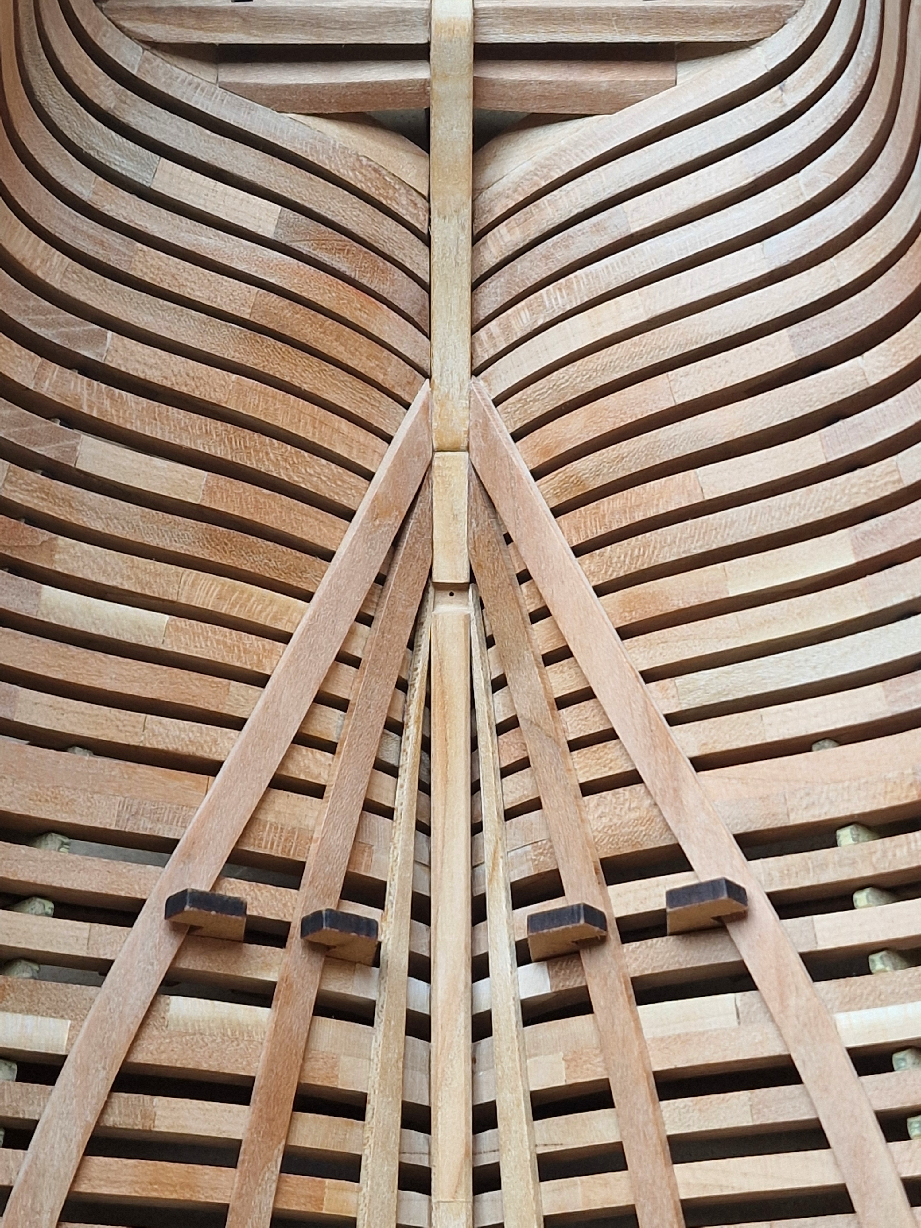
First, I drilled holes in the grooves with a diameter into which the pin passes. And with this mace he fixed the part in place. There are three such places.

Then, from the stern, I applied a strip of CA to Keelson himself. The pin next to the glue must be threaded through in order to insert its tip into the keel and lower the Keelson into its place along the pin. This makes it easier to position it with a fast glue.
For now, while the CA glue sets, the entire Keelson is laid on the frames, parailly passing pins into the holes for better positioning of the second edge. Well, all that remains is to hold Keelson so that the caday is completely frozen (5-7 minutes). And here is the finished result.


23.05.2025
But for this you need to add elements to the slipway. These are hook positioners for 3 pairs of power boards.

Before fixing, I cleaned a little from the soot of the place of contact
with the boards and made pins for fixing from a 3mm cylindrical
workpiece.
Then I temporarily removed the middle part of the side positioners to make access to the attachment point.

After that, it was possible to fix the "hooks" on the pins.


Fixed so far 2 lower levels. I will fix the upper one later. And this is how it all looks.

Parts DL 30 (Trickstuff over the floor heads) Longer and therefore they need to be adjusted according to the meter. Better to start from the front. The end of these parts must be at the Keelson termination point (BL12).

We remove the excess and take into account that the rail goes at an angle, so the slice should be with this calculation.

So the opposite end, the stern side.

The rail is longer, we will cut it so that its end falls on the connection of the BL15 and ID14 parts (a small step).

We cut again and take into account the angle of rotation of the rack. The board should have this end.

And when pressed - the planes for gluing should converge without a gap and the end of the part should reach the step on the keel.

This is important in order for the top and bottom boards to dock
correctly and in the right place. And here is the result after fixing.
Symmetry is our everything!


First, I put the board in the hooks and then shifted it half its width higher along the frames. This is necessary to put dots with a pencil along the entire length of the board. That is, when we shifted it, we visualized exactly the center of the board.
Then I shifted the board even higher (along the frames) so that it was held only by the ends of the hooks.
Then I applied a drop of glue from a syringe to each frame, PVA TiteBond II to the dots that we had previously drawn with a pencil. And immediately applied glue CA gel on both ends of the board (those that we had previously polished).
Then the board is neatly shifted to its place, positioned at the ends and pressed well near the place of CA glue with your thumbs. The remaining fingers press the middle part of the board. The CA glue sets quickly, so after a couple of minutes we transfer all the effort to the middle part and hold it for another 5-7 minutes. That's all! You can still stick wedges between the board and hooks in parallel, this will reduce the number of places where you need to press your fingers.

The method is working. Fast and most importantly - neat. Since the only place where the glue can come out a little is CA gel, but it will be perfectly scraped with a blade and removed without a trace with fine sandpaper. And unlike PVA, it does not change color after coating with oil. And the point-spread PVA does not go beyond the glue stain and does not give leaks. Which makes me very happy.
24.05.2025
The second pair of boards already exists, now we will glue the first pair (those closer to the keel, Limber strike).
And to position the boards in the exact place, I used the stationery clips, plus wood (b - in the photo below). Which corresponds to the distance from the keel to the boards on the Mast step (a - in the photo). By the way, on the Mast step there is a ledge (with - in the photo) that needs to be combined with a chute on the keelson.

And now, you can glue the boards and just rest against the clips, and they will be glued evenly.

By the way, the gluing technique is the same. I dot the TiteBond II glue on each frame, except for the most lateral ones. I apply CA gel on the bottom. My wife helps me. While I hold the CA point - it holds the board over the PVA. And as soon as the CA sticks, I hold the place where the PVA was for another 5 minutes and everything is ready. Fixation without devices takes 6-7 minutes and you can work further.

And here is the finished symmetrical result.


And after that I glued the Mast step.

It is better to adjust them also from the front.

We still remember that the board is spinning in a spiral and you need to make a bevel in order to press it like this without a gap. And the joint hit as in the photo.

But you need to take into account a very vague moment. The ket includes a positioner (part CL 46).
It is necessary that this part passes between the 22th and 23th frames
and gets into the groove for the 3rd beam of the lower holly. That is,
you need to adjust the board in front so that this happens!

Well, at the back, similarly, we also cut off until we connect with the second pair of power boards. again, not forgetting the bevel.


By the way, before that I glued boards without heating, water, steam or
iron. But in this situation, the boards go on a screw and it is
difficult to keep such tension for a long time. Therefore, at first I
gave the boards the correct shape.

Only the ends of the boards were dipped in boiling water for a minute
and immediately hot irons along the plane, I twisted the board with a
screw and bent it a little. But you need not overdo it, otherwise you
can break it. Then you definitely need to walk with sandpaper, because
lint rises from the water.
The fixing method is still the same. Point PVA for each frame and CA at
the edges. I press the edges while the spouse helps to hold the middle
part, and then I still hold it for 5 minutes and you're done. There are
no leaks from the glue, and everything is held flawlessly. And here's
the result.


Looking like lemon slices, or carom, or melon... well, in short, something edible resembles)))

Next in line are Breast hooks and the top pair of powerboards - Beam shelf\Deck clamp (which, in fact, most likely go as one board).
Today there will be two parts at once. 1/2
And in addition to the last post I will add.

The technique is simple. It is necessary to use a special thin spout and apply glue to the corner between the parts so that the glue penetrates capillary between the parts and thus glues them together when solidified. To speed up the process, an aerosol activator for the CA adhesive can be used.

Glue elimination technique. It is necessary to scrape the remains of the glue with the plane of a straight scalpel. Final polishing with sandpaper. And here's the result. As nothing happened.

It is better to apply very little, but twice than once but a lot and pour everything around.
So, we continue. Next up is the top belt, which will hold the main deck beams. First you need to prepare the blanks...

Then I made a template from a thin rail and bent it along the profile of a real workpiece.


And most importantly, it was necessary to check whether the board was becoming correct and whether the slots of the positioner coincided.

It is necessary that the CL47 template falls between the 22m and 23m
frames and fits into the groove of the power board. I will check this
again with real details.
You also need not to forget about the checkpoints. Behind...

The part should become so that it is 2 mm before the beam.

And in front you need to make a wedge so that the part fits into place correctly.

Then I glued all the 3 parts of each CA board with gel on a flat isolated plane...

... and polished the surfaces.

Then, so that the boards do not crack - you had to soak them in boiling water for 15 minutes (maybe I don't remember anymore).

I used a stove top. And it is important that the glue does not spread
from the temperature and bending - I clamped the place where the joint
was clamped. (one point - isolate the clamps with something, otherwise
traces in the water from the metal on the tree may remain!).
Then I removed the excess water and placed the parts in the case,
bending very carefully, resting the files on the part for primary
stabilization.


Then I fixed in several places at equal intervals with plastic clips (ties).

Outside, they held onto wedge-shaped wooden blocks. If you move the bar from the thin to the thick side, you can control the degree of tension on the screed.

Forgot to mention!!! This is all we do WITHOUT GLUE!!! And that's why!
According to the CL47 positioner, the beams should stand in a certain
way and I saw that the board was shifted 1 mm backward. And I understood
that it could (and should) be so, because I cut 1 mm of the board in
front in place...

Loosened all clamps and moved the board forward by 1 mm.


As I wrote above. You need very liquid CA (very). And a special spout.
We apply a small amount to please between the parts (it is better twice a
little more than once, but with an excess).

After that, you need to polish the part, remove the rest of the glue and the raised pile from the water.

And almost everything is perfectly clean. It was possible to remove all the surpluses, since there will be two levels of parts on top - they will completely cover all this. But if there was an open place - I would not pour glue so much, and cleaned better, but here it is useless.

As a result, one side is completely ready. It will only remain on the other side.
And here is the result of the work.


27.05.2025
Well... I can say that I'm done with the bases. I removed all the
auxiliary holders in the slipway and now I can take the ship out with
the outside facing up. Well, for now, here's the result of the work up
to this point.
There are 518 parts on board and 57 days of pleasant work on the hobby... let's move on!


This is why this part does not need to be glued and it is advisable to cut it (as I previously showed it all in the review). Because when removing the ship - these parts are easier to remove. We won't need them anymore.

Voila... and the hull is free!
By the way, it is in this form (only without a keel) that it will soon
be scanned. I will tell you everything in more detail, but you will
remember this picture...

How cool he is after all... The body looks cool in the hand, I really like it... and that's before grinding!


The manufacturer thought out the slipway very well. If you turn over the lid with the model and insert its top with your feet, you can snap the lid with the same clips so that it sits firmly in its place.


And in this form, you can safely grind the case. A little tip: so that the slipway does not drive around the table - it can be fixed with clothespins or clamps.


Next...