
перевод
Сhapter 3. Decks
As I mentioned earlier, I hadn’t worked on the battleship model for 10 years.
But due to the war, I took the model from my parents' house and started calculating the decks. In most kits, the decking is overly simplified. The planks included are too wide for the scale—sometimes 2 or even 3 times wider. Since 2023, I’ve fully transitioned to using John McKay's 'Anatomy of the Ship.' I had scans of the book from the internet, but I still ordered a copy through friends in the USA, as it wasn’t available in Ukraine. As I mentioned before, I scanned this book and combined the necessary fragments to print the plans. It came out to 4 sheets, but I think I already talked about that))). So, armed with calipers, I started calculating the proportions of the deck planks.
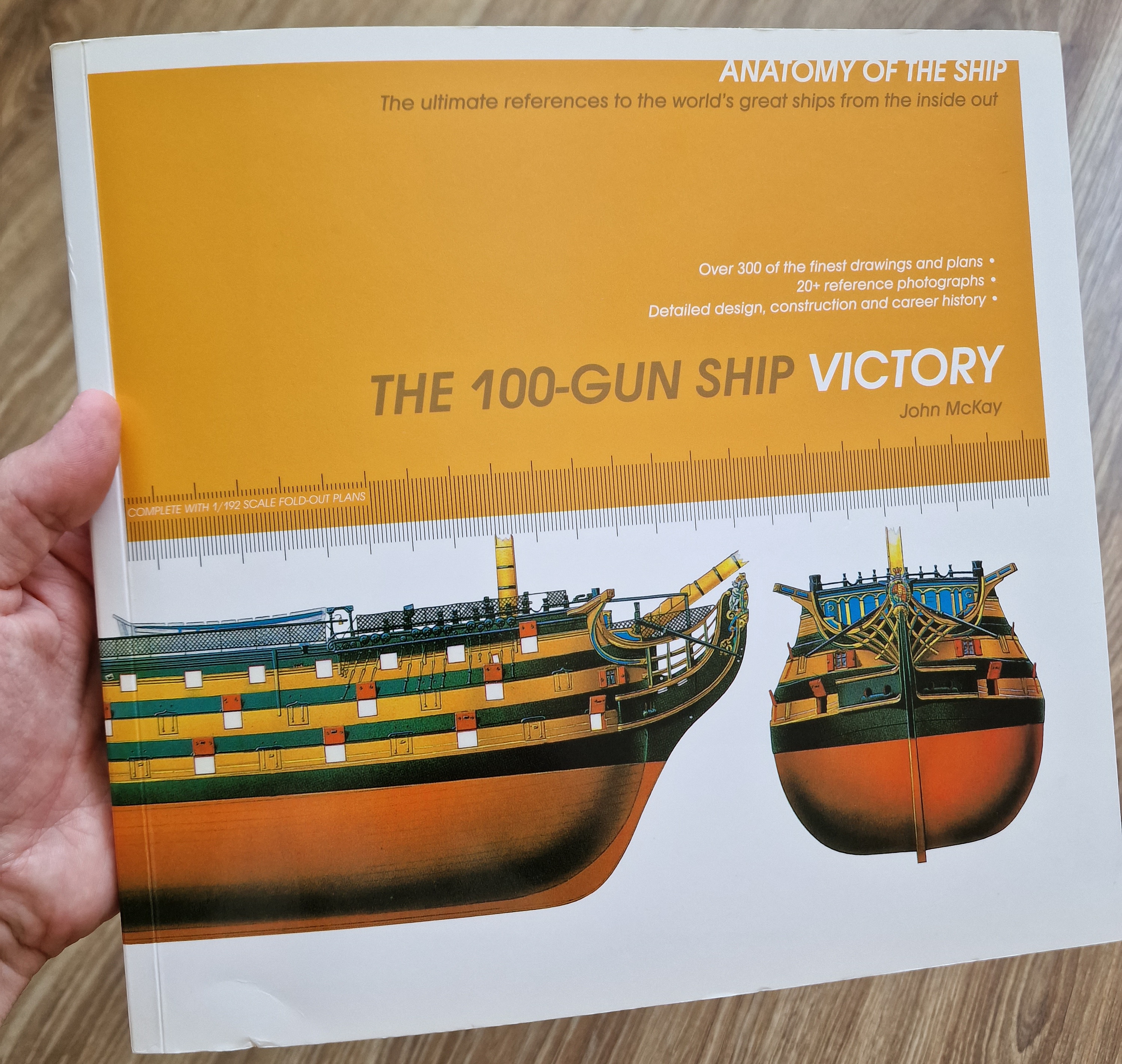

I scanned it, and after spending several days working in Photoshop, I managed to assemble the necessary fragments into four massive blueprint images. I printed these four calibrated drawings at A0 size. In this way, I created 1:1 scale blueprints matching the size of my finished hull.
Consequently, the entire subsequent build will rely not on the Mantua plans, but entirely on the *Anatomy*!


 To reiterate, I calibrated these plans to match the dimensions of the hull I had already built using the plans printed from the Mantua kit. In other words, if someone else’s scale differs, these specific plan dimensions won't be applicable.
Here is how I did it: I used A0-sized sheets as the base in Photoshop. I calculated the length in millimeters between specific points on my model and the corresponding points on the "Anatomy" plans, then adjusted them to match. Once I determined the correct scale factor for importing the scanned images into the Photoshop file, I applied that scale immediately so that everything imported at the right size; all that remained was to position them correctly. I adjusted higher-resolution images (which had a different scale) to fit the general layout. Consequently, after printing these four sheets, I had a set of full-scale plans in hand. Now, I can determine the dimensions for any hull detail, spar, rigging component, etc., using a standard caliper or ruler (though the caliper is more precise).
Paradoxically, almost all the key dimensions matched up—gun port sizes, deck widths and lengths, the stern gallery, the head, and so on—all aligning within a small margin of error. Now, when I calculate dimensions for fittings, spars, cannons, and the like based on the "Anatomy" plans, the parts fit perfectly into the completed hull. This is my response to skeptics who claim that building from kit plans is a bad idea and doomed to failure. I partly agree that starting with accurate plans is ideal, but not everyone has access to them, and starting with kit plans is easier. I also want to dispel the skeptics' claim that gluing the planking over a solid filler base is a recipe for failure... well, guess what! More than 10 years have passed, and nothing has come loose anywhere. Upon very close inspection and final polishing, I did notice a couple of planks that seemed a bit loose, but I suspect they were like that from the start. It’s an easy fix—just a drop of cyanoacrylate at the joint, and that’s it.
If I have time, I’ll revise the section on working with the plans, because if I were starting this project today, I would definitely begin with the anatomy!
By the way, according to my calculations, the scale actually turned out to be 1:79 rather than 1:78... This likely happened because I scaled up the Mantua plans when printing them on A0 paper, but it doesn't really matter—the difference is negligible.
Consequently, the entire subsequent build will rely not on the Mantua plans, but entirely on the *Anatomy*!


 To reiterate, I calibrated these plans to match the dimensions of the hull I had already built using the plans printed from the Mantua kit. In other words, if someone else’s scale differs, these specific plan dimensions won't be applicable.
Here is how I did it: I used A0-sized sheets as the base in Photoshop. I calculated the length in millimeters between specific points on my model and the corresponding points on the "Anatomy" plans, then adjusted them to match. Once I determined the correct scale factor for importing the scanned images into the Photoshop file, I applied that scale immediately so that everything imported at the right size; all that remained was to position them correctly. I adjusted higher-resolution images (which had a different scale) to fit the general layout. Consequently, after printing these four sheets, I had a set of full-scale plans in hand. Now, I can determine the dimensions for any hull detail, spar, rigging component, etc., using a standard caliper or ruler (though the caliper is more precise).
Paradoxically, almost all the key dimensions matched up—gun port sizes, deck widths and lengths, the stern gallery, the head, and so on—all aligning within a small margin of error. Now, when I calculate dimensions for fittings, spars, cannons, and the like based on the "Anatomy" plans, the parts fit perfectly into the completed hull. This is my response to skeptics who claim that building from kit plans is a bad idea and doomed to failure. I partly agree that starting with accurate plans is ideal, but not everyone has access to them, and starting with kit plans is easier. I also want to dispel the skeptics' claim that gluing the planking over a solid filler base is a recipe for failure... well, guess what! More than 10 years have passed, and nothing has come loose anywhere. Upon very close inspection and final polishing, I did notice a couple of planks that seemed a bit loose, but I suspect they were like that from the start. It’s an easy fix—just a drop of cyanoacrylate at the joint, and that’s it.
If I have time, I’ll revise the section on working with the plans, because if I were starting this project today, I would definitely begin with the anatomy!
By the way, according to my calculations, the scale actually turned out to be 1:79 rather than 1:78... This likely happened because I scaled up the Mantua plans when printing them on A0 paper, but it doesn't really matter—the difference is negligible.
___________
04.2023
But I'll talk about that a bit later. For now, I’ve made some changes to the hull.

The changes will affect the upper deck. I didn’t make any changes to the front part. The wall here will remain. The space between the front two pairs of ports was designated for the sick bay. This wall was constructed to provide warmth and comfort to the wounded or sick. I will continue to work on this wall.

As for the rear wall, I moved it back by one more port. This way, all the ports between the partitions will remain without covers, while the ones in front and behind the partitions will have covers.

Сначала я убрал стенку и срезал кусочки от двух планок-держателей псевдопушек...

For this, I removed the wall again and trimmed small sections from the two planks that hold the dummy cannons.

Then I extended the deck and installed a new bulkhead. In this case, my mistake was that I should have installed the wall behind the frame. Because there is little space between it and the gun. However, visually it appears very deep and will not be visible.
After that, I divided the quarterdeck into two parts along this frame and glued the rear part in its place. The front part will be removable.

And as a small detail, I slightly adjusted the openings for the lower hatches leading to the middle deck. It will not have any cladding, just painted black, as this area will hardly be visible.

04.2023
But I'll talk about that a bit later. For now, I’ve made some changes to the hull.

The changes will affect the upper deck. I didn’t make any changes to the front part. The wall here will remain. The space between the front two pairs of ports was designated for the sick bay. This wall was constructed to provide warmth and comfort to the wounded or sick. I will continue to work on this wall.

As for the rear wall, I moved it back by one more port. This way, all the ports between the partitions will remain without covers, while the ones in front and behind the partitions will have covers.

Сначала я убрал стенку и срезал кусочки от двух планок-держателей псевдопушек...

For this, I removed the wall again and trimmed small sections from the two planks that hold the dummy cannons.

Then I extended the deck and installed a new bulkhead. In this case, my mistake was that I should have installed the wall behind the frame. Because there is little space between it and the gun. However, visually it appears very deep and will not be visible.
After that, I divided the quarterdeck into two parts along this frame and glued the rear part in its place. The front part will be removable.

And as a small detail, I slightly adjusted the openings for the lower hatches leading to the middle deck. It will not have any cladding, just painted black, as this area will hardly be visible.

05.2023
In the photo above, you can see that I have already marked the connections of the deck boards. Based on the printed drawings from the anatomy book, I measured the width and length of the deck board. For my scale of 1:79, these dimensions were 2.5x80 mm.
I used pear veneer for the cladding. Unfortunately, I didn't have solid material of that type. I don’t enjoy working with veneer, but it is what it is. To measure these 2.5 mm evenly, I created a jig. Measuring 2.5 mm can be quite inconvenient, and sooner or later, errors creep in. This jig was very helpful for me.


The device is very primitive. The thickness between the blades of the utility knife is static, and the distance between the tips of the blades is exactly 2.5 mm. Then I mark multiple distances with a puncture at the same time.

I cut the veneer in the usual way—using a knife along a ruler. It took a long time, but it was effective! By the way, the veneer was glued with double-sided tape, and the ruler was additionally fixed with weights from dumbbells.

I started testing on the small deck of the galley. I didn’t do it without mistakes, which I will discuss later.
First, I prepared the base. By the way, there is a significant error in the anatomy drawings. It appears in almost all "boxes" and later caused me some problems. The mistake is that the deck on the galley is not a continuation of the deck with the guns, but rather an additional level above the deck.

But at that moment, I didn't notice this and, accordingly, worked without this small deck. However, looking ahead, everything turned out fine anyway. Many people do it that way.
First, I raised the front edge to replicate the curve of the deck and covered the holes for the knighthead. After that, I made a plate to which I will glue the decking.


I cut holes for the bowsprit and started laying the deck. Below, I will explain the technology I used for gluing. (The black cylinder is a charcoal pencil; later in the text, it will become clear why I used it.)

And the first mistake was that I needed to glue all the veneer strips in one direction, without flipping them 180 degrees or upside down. Because in the dry version, everything seemed more or less fine, but...
 ...after applying the oil, the color became pronounced. And due to the difference in the grain, some strips started to stand out from the overall mass.
It's good that I applied oil to this fragment and noticed it early, rather than after I had finished all the decks. The second positive aspect is that this deck is not very visible, and looking ahead, under three layers of oil and after some time, the difference was not so noticeable. However, it's still important to follow the principle. I will describe below how I marked the strips of veneer to glue them strictly one way, without flipping them either vertically or horizontally.
At the same time, I continued to refine the hull according to the anatomy drawings. I adjusted the old proportions of the openings from the kit to match the correct dimensions. Quarterdeck...
Before:


After:
Finally, the decking is done.
While laying the planks, I marked a dot on one side to ensure they all faced the same direction, avoiding any color differences.

For convenience, I glued the upper deck in two parts on a paper base, separately from the main deck. This allowed me to properly sand the surface and easily attach the strips. I created the caulking effect using a regular charcoal pencil, coloring one long edge and one short edge on one side.

I glued the strips using PVA and a hot iron, welding them in place to speed up the process.

After sanding and fitting, the two halves of the deck were glued in place. To speed up the process, the area that won’t be visible was glued without joints. Please forgive me for that )))


05.2023
Well, let's continue with the decks. Up next is the quarterdeck.
As I mentioned earlier, I divided this deck into two halves. The rear part is glued statically, while the front part will be removable. I also reinforced the inner section to strengthen the curve of the deck.


Then I cut and glued a base from veneer for the deck planking. The planks will be glued onto this base, and the entire assembly, with the planks attached, will be adhered to the main plywood section.
 I didn't want to glue the planks directly onto the hull. It's inconvenient and difficult to sand. By doing it this way, I can glue everything on the table, comfortably. I marked the base for the planking with a deck plank length of 80 mm. I kept everything consistent across all the decks, only adjusting slightly at the ends and where the hatch openings were. I understand that the beam spacing varies on each deck, and even in the anatomy, things don't always match up perfectly. But since this model isn't for a competition, I allow myself these simplifications. The beam spacing ended up being 19 mm.


After that, I started planking the deck. I used both weight presses and the iron to help with the process. I'll go into more detail about the method when I work on the poop deck.


To take a break from the planking, I decided to work on the mast steps. First, I checked the angle of the bowsprit for accuracy.

The angle was 30 degrees, and I shaped the hole for the bowsprit in the small forward deck.

And now, the interesting part.
I made the mast sockets from aluminum tubes. The entire principle of how the masts are connected to the hull will become clearer later on. But briefly, the tubes with a diameter of 10 mm were glued into the hull for the bowsprit and the two forward masts, and 8 mm for the mizzenmast. The masts themselves will have tubes with a diameter 2 mm smaller, which will fit into the tubes in the hull.
This will ensure a perfect fit for all the masts (since each has a different angle), and more importantly, it allows me to remove the masts easily without gluing them. This greatly increases the repairability in case of any damage.

I fitted all the tubes at once, with the inner tubes (mast imitations) inserted, which stuck up about 30 cm. By adjusting these protruding parts, I was able to set the correct angle for each mast. I glued everything using 5-minute epoxy, fine-tuning the angle by inserting toothpicks into the holes.

Then, the toothpicks and glue were sanded down to the level of the deck. As a result, the tubes are firmly glued into the hull, into which smaller diameter tubes will later be inserted. This will ensure a perfect fit, without the need for glue.

For the bowsprit, the profile of the inner tube ended up looking like a needle tip)))

To wrap up the lower tier, I decided to finish the sides from the inside. I covered the lower side with rails made from the veneer of enegri wood. The wood is specific, but since this area will be little visible, it will do just fine. It looks good when dry, good in oil, but under bitumen, the texture is very pronounced. I will show this later.


А когда это все высохло - заменил в средней части палубы боковую рейку.


The rail in the corner, between the deck and the side made of daru. I used this material for the entire upper side.


The cladding of this side will hold the deck in place. It forms a groove into which I slide the deck, securing it there.
 Oh, I forgot to mention. I redesigned the stand. It’s still temporary like the previous one, but now it has a perfect fit. When the ship is on it, it is perfectly level along all axes.

And finally, to securely fix the deck in place, I screwed it down with screws. This is temporary and will allow me to work conveniently on the hull.


A small bulwark has appeared in the front section of the deck, and for now, I have finished with this deck. In the next part, I'll cover the poop deck and provide a detailed description of the process of gluing the planks.
06.2023
And finally, I planked the uppermost small deck, the poop deck. Starting from the center, I laid down the first plank to ensure the straight line didn’t shift. Then I worked outward in both directions, following a stepped pattern. The side planks were done with some loss. Afterward, everything was sanded down. I glued the planks using PVA, securing them with an iron. The plank ends were colored with a charcoal pencil to imitate caulking.


I made the finished deck so that it would fit between the beams and small bulwarks, sliding into this space from front to back.


What else did I do with the decks? I cut out holes for the masts and hatches. Behind the helm, I made an opening for the staircase. Additionally, I glued the baseboard under the doors below the poop deck.


After that, I was able to install the mock masts to check their angle and position. As I mentioned earlier, I had glued aluminum tubes into the hull. Now, I inserted smaller-diameter tubes into those, which simulate the masts. What do you think of the result?


Here, it's clearly visible how much the rear masts are tilted.
While laying the planks, I marked a dot on one side to ensure they all faced the same direction, avoiding any color differences.

For convenience, I glued the upper deck in two parts on a paper base, separately from the main deck. This allowed me to properly sand the surface and easily attach the strips. I created the caulking effect using a regular charcoal pencil, coloring one long edge and one short edge on one side.

I glued the strips using PVA and a hot iron, welding them in place to speed up the process.

After sanding and fitting, the two halves of the deck were glued in place. To speed up the process, the area that won’t be visible was glued without joints. Please forgive me for that )))


05.2023
Well, let's continue with the decks. Up next is the quarterdeck.
As I mentioned earlier, I divided this deck into two halves. The rear part is glued statically, while the front part will be removable. I also reinforced the inner section to strengthen the curve of the deck.


Then I cut and glued a base from veneer for the deck planking. The planks will be glued onto this base, and the entire assembly, with the planks attached, will be adhered to the main plywood section.
 I didn't want to glue the planks directly onto the hull. It's inconvenient and difficult to sand. By doing it this way, I can glue everything on the table, comfortably. I marked the base for the planking with a deck plank length of 80 mm. I kept everything consistent across all the decks, only adjusting slightly at the ends and where the hatch openings were. I understand that the beam spacing varies on each deck, and even in the anatomy, things don't always match up perfectly. But since this model isn't for a competition, I allow myself these simplifications. The beam spacing ended up being 19 mm.

After that, I started planking the deck. I used both weight presses and the iron to help with the process. I'll go into more detail about the method when I work on the poop deck.


To take a break from the planking, I decided to work on the mast steps. First, I checked the angle of the bowsprit for accuracy.

The angle was 30 degrees, and I shaped the hole for the bowsprit in the small forward deck.

And now, the interesting part.
I made the mast sockets from aluminum tubes. The entire principle of how the masts are connected to the hull will become clearer later on. But briefly, the tubes with a diameter of 10 mm were glued into the hull for the bowsprit and the two forward masts, and 8 mm for the mizzenmast. The masts themselves will have tubes with a diameter 2 mm smaller, which will fit into the tubes in the hull.
This will ensure a perfect fit for all the masts (since each has a different angle), and more importantly, it allows me to remove the masts easily without gluing them. This greatly increases the repairability in case of any damage.

I fitted all the tubes at once, with the inner tubes (mast imitations) inserted, which stuck up about 30 cm. By adjusting these protruding parts, I was able to set the correct angle for each mast. I glued everything using 5-minute epoxy, fine-tuning the angle by inserting toothpicks into the holes.


Then, the toothpicks and glue were sanded down to the level of the deck. As a result, the tubes are firmly glued into the hull, into which smaller diameter tubes will later be inserted. This will ensure a perfect fit, without the need for glue.

For the bowsprit, the profile of the inner tube ended up looking like a needle tip)))

To wrap up the lower tier, I decided to finish the sides from the inside. I covered the lower side with rails made from the veneer of enegri wood. The wood is specific, but since this area will be little visible, it will do just fine. It looks good when dry, good in oil, but under bitumen, the texture is very pronounced. I will show this later.


А когда это все высохло - заменил в средней части палубы боковую рейку.


The rail in the corner, between the deck and the side made of daru. I used this material for the entire upper side.


The cladding of this side will hold the deck in place. It forms a groove into which I slide the deck, securing it there.
 Oh, I forgot to mention. I redesigned the stand. It’s still temporary like the previous one, but now it has a perfect fit. When the ship is on it, it is perfectly level along all axes.
And finally, to securely fix the deck in place, I screwed it down with screws. This is temporary and will allow me to work conveniently on the hull.


A small bulwark has appeared in the front section of the deck, and for now, I have finished with this deck. In the next part, I'll cover the poop deck and provide a detailed description of the process of gluing the planks.
06.2023
And finally, I planked the uppermost small deck, the poop deck. Starting from the center, I laid down the first plank to ensure the straight line didn’t shift. Then I worked outward in both directions, following a stepped pattern. The side planks were done with some loss. Afterward, everything was sanded down. I glued the planks using PVA, securing them with an iron. The plank ends were colored with a charcoal pencil to imitate caulking.


I made the finished deck so that it would fit between the beams and small bulwarks, sliding into this space from front to back.


What else did I do with the decks? I cut out holes for the masts and hatches. Behind the helm, I made an opening for the staircase. Additionally, I glued the baseboard under the doors below the poop deck.


After that, I was able to install the mock masts to check their angle and position. As I mentioned earlier, I had glued aluminum tubes into the hull. Now, I inserted smaller-diameter tubes into those, which simulate the masts. What do you think of the result?


Here, it's clearly visible how much the rear masts are tilted.