
перевод
In fact, the Victory model is my second model, but my first more or less serious work, although I had previously built the Brig Mercury.
A few words about that very first model. I started building the brig in late 2002. Back then, there were no proper drawings, no knowledge, and not even anyone I could ask about everything. Forums, if they existed, I didn't know they existed. It was only in 2009 that I had at least some knowledge. It was during this period that I created my own forum, which eventually became one of the largest in Ukraine. But due to the russian attack on Ukraine, the forum ceased to exist...
I built the model using drawings from the internet. These were four sheets showing the parts and their dimensions. The drawings were of poor quality and not to scale. I built it from balsa (an ultra-light wood used primarily for building model airplanes, which is what I did until 2002). Naturally, when I realized that building like that, especially with such a material, was impossible, the project was abandoned. But I still have something to show. These are, one might say, my first steps in ship modeling:


This is me back in 2003...
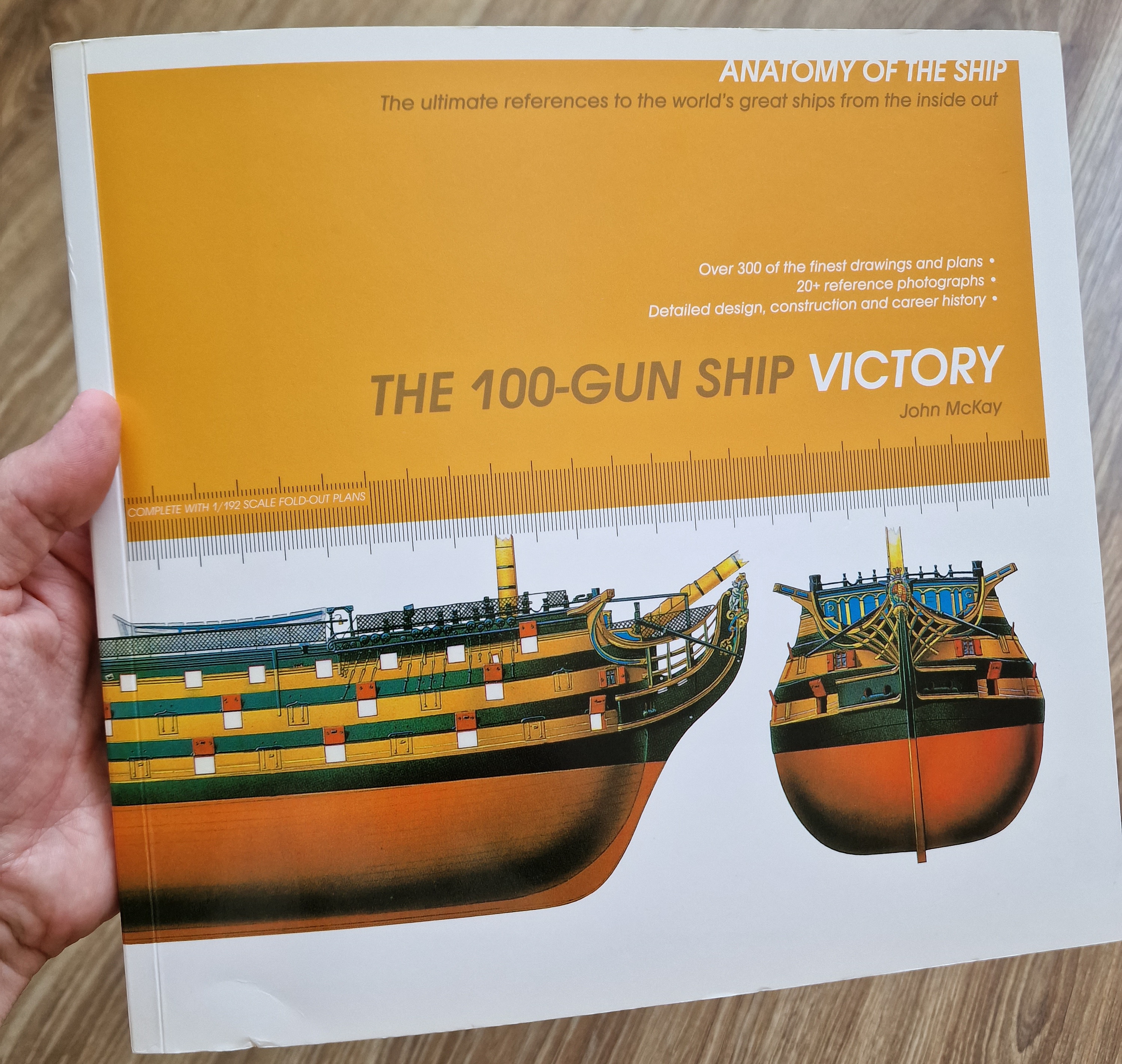
But back to HMS Victory...
Work on the Victory project began on October 1, 2009, but construction was put on hold in 2013, until 2023 (that's 10 years, by the way).
In the review presented here, the first two parts were completed before the break, and the rest were completed starting in 2023... and until the second break, as I started a new project, Cutter Alert 1777.
A brief overview of how it all began...
Like many aspiring modelers, I immediately wanted to build something grand and large... and like many, I chose the Victory model. But I couldn't afford a kit (I really wanted Caldercraft (JoTiKa)), so I found the plans from Mantua. They turned out to be simple and fairly complete. I made some adjustments and refinements (I wrote about all of this below)... and started building. And later, after a 10-year hiatus, I bought the book...
These blueprints are scaled to fit the dimensions of my specific model. That is, they're at the same scale (1:79) at which I printed the Mantua skeletal body blueprints! If you're interested, you can download them from Google Drive.

I made the drawings to create the correct-sized parts. I already had the body ready, and to avoid calculating the dimensions of each part individually, I used Photoshop to scale and assemble all the angles for all the parts I needed. After printing 1:1, I could use a regular ruler to take the original dimensions of all the parts directly from these drawings.


From these plans, I practically made the entire hull, decks, and everything on them... but with the start of the new project, I realized I wouldn't make any matches or rigging for this model, as it would take too much time and effort, which, in my opinion, isn't very practical, given the level of this model. Everything will end at the stage of a fully finished hull with a bowsprit and mast fragments. Many parts will be made of plastic. I personally modeled many of the parts in a 3D program and printed them on a 3D printer. This made perfect sense for this particular project, allowing me to finish it to a finished body without wasting too much time. I also achieved good results in preparing and painting the plastic parts. And at this scale, it looks more than respectable.
Below are my corrections and, as promised:
N.B. All improvements and corrections are my own and are not a 100% template. This is a collection of tips for improvement and preparation for work. Therefore, it is up to you to decide whether to heed them or not. I would also appreciate your comments and corrections. If you noticed anything else that I missed, please write in this blog. Thanks in advance.
Every project starts with drawings! And it's no secret that the better the drawing, the fewer problems there will be later. Again, I used Mantua drawings as a basis. But! These drawings are good only for two reasons: scale (1300 mm length) and, most importantly, they include drawings of all the hull parts, something that JoTiKa, for example, doesn't have. But at the same time, Mantua has greatly simplified everything. Neither the spars nor the rigging are any good!
To put it briefly: thanks to Mantua for the hull, JoTiKa for the spars, rigging, and the resemblance to the original, and Mamoli for the visualization of the assembly components.
So, let's get back to the basics. The frame by Mantua (the drawings for which can be found on the website) is quite good, but! It's all the same BUT. They're full of errors. We'll try to fix them all. Many people rack their brains and immediately saw and chop, only occasionally glancing at the drawings. Although this is very, very unnecessary! Because underestimating the importance of this step in construction can be very frustrating later on.
I'll explain the inconsistencies, simplifications, and omissions in these drawings one by one. Naturally, everything is illustrated. In Figure 1, I'll replace part 25 with two three-dimensional blanks, which will be used to bend and glue the slats (this will be visible during construction). However, before this, the knävdiged (front part) will need to be cut off along the pencil line; it will be glued back on at the end of the planking. I'll also need to modify part 1. I'm not sure what the manufacturers were looking at, but the bowsprit will pass through this very part during assembly. Therefore, as shown in Figure 1, we'll reinforce part 16 with a "U"-shaped protrusion, removing material where it shouldn't be. This will prevent us from doing this on the model, risking damage. And on part 16, we'll make a "C"-shaped cutout, as shown in Figure 9.

*Left-click on the image to open the full-size image in a new tab.
Figure 2 shows how the sternpost (the plank to which the rudder is attached) should look. The rudder itself shouldn't be flush with the keel (it should be slightly higher). You can also see how part 14 should be trimmed (the section to be removed is indicated by the hatching). However, part 18 will be completely omitted! The stern will be manufactured completely differently (all will be visible in the overview).

The frames were also modified. Figure 3 shows that the portion that will become the side has been reduced in thickness. This applies to frames 8 and 9.

And the 5th, 6th and 7th will be changed as shown in Figure 4.

Now, about the discrepancies. Figure 5 shows how much the slot for the 4th and 5th frames needs to be moved back: 1.5 mm and 0.7 mm.

As we know, a ship's masts aren't always at a 90-degree angle to the deck. Victory only has a forward foremast, which isn't angled, as shown in Figure 6...

The mainmast has a rake of 2 degrees, as shown in Figure 7. This was not taken into account by the drawing company, and corrections will be made later.

The mizzenmast is angled even more, 3 degrees aft, as shown in Figure 8.

So it turns out that there are no problems in the front, all the holes are in place and everything matches (Fig. 9)...

But then things get more complicated. In part #15, the hole shifted by 1 mm, and in part #16, by a full 3 mm. (Fig. 10)

The same applies to the rear of these parts: 1 and 3.5 mm, respectively. (Fig. 11)

Even higher (detail 29) – even more deviation – by the entire mast body, 8 mm. (Fig. 12)

But the most interesting thing happened with the 28th piece. Here, all the holes lined up, taking into account the tilt!! (Fig. 13, 14)…


However, the rear section is completely misaligned. It overlaps frames 10 and 11 by 5.5 and 6.5 mm. Therefore, the area marked in pencil must be removed (Fig. 15). The grooves with frames 8 and 9 are also misaligned, but even without this, they only need to be made 2 mm deeper and 5 mm forward of the incorrect position (Figs. 14, 15).

The lower deck has the same problem. (Fig. 16) The hole is 2.5 mm to the rear and the grooves are only 5 mm deep (for the frame cutout, see Fig. 4)

Also missing from the drawings are parts #167 and #387 (JoTiKa drawing), which are actually very important! And the ports aren't indicated, indicating they're different. Figure 17 shows that the left port is for a door that fits into a groove, while the right port is without a door, and the groove (frame around the opening) is unnecessary.

I'd also like to return to the body, specifically part #14. I prepared grooves in advance for the base on which the model will stand (Fig. 18).

I also wanted to point out this discrepancy with the original. The ladder that descends to the lower deck in the drawings (on the right) is one flight further from the bell tower. Although the correct drawing (on the left) would be on the first flight. The second pair are positioned correctly (I didn't show them) (Fig. 19).

Also, the Mantua drawings don't include parts 660, 162, and 244-247, as shown in Fig. 20 of the JoTiKa drawings. Plus, the hatch (left) is longer. I've adjusted it, as shown in Fig. 21. As for Mantua's simplification of removing the ladder to the deck even lower and replacing it with doors, I won't do that. Both ladders will be included! Consequently, part 16 will be shorter. Part 16 will be interrupted from frames 4 to 8, as shown in Fig. 21. I assure you, this won't affect the rigidity of the structure or any other properties! Everything will be compensated for by parts #26.


My first addition will be the changes I made during the model's construction.
To prevent parts #27 from being visible through the middle deck, I extended the lower deck by one more cannon on each side (more on this in Part 2 of the review). As for the drawings themselves, I made this.


I cut out the inner section of frame #4 (similar to frame #5), and in frame #8, as shown in the second photo. For those who want to do the same, but with more experience, it's best to initially calculate the deck length a bit longer (see Part 2 of my review for a similar example).
Next...